Passaic River Deep Braced Excavation Modeling
- Our Projects
Passaic River Deep Braced Excavation Modeling
Project Overview
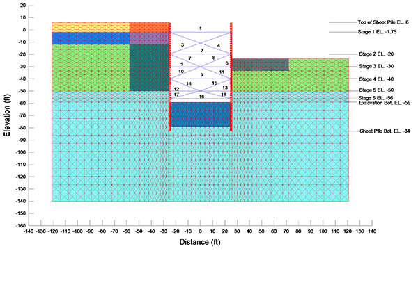
The project involved two parallel rows of sheet piles — one driven along the riverside and the other driven 50 ft inland. The riverside sheet piles were to be driven in the water along an existing bulkhead. Excavation to remove contaminated soil, as well as the existing bulkhead, was proposed between the two sheet pile walls to a maximum depth of 65 ft. As the excavation was to proceed, internal bracings (waler and strut system) spaced at 25 ft were to be installed at various depths (as shown in the finite element mesh image). After removal of the contaminated soil, the excavation was to be backfilled to its original grade.
In general, the design of braced excavations is usually performed by empirical methods. Such an approach, however, raises questions about the deformation behavior of the system due the specific setup involved. Application of the finite element method (FEM) to this project, however, bridged the gap in the empirical methods and provided a calibration tool for detailed design optimization.
Plain strain FEM analysis was performed using the SIGMA/W computer program. A linear-elastic soil model was used in combination with an elastic perfectly plastic model having a modified Mohr Coulomb yield criterion. These parameters thus eliminated unrealistic tension behind the sheet piles and initiated yielding.
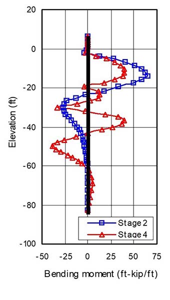
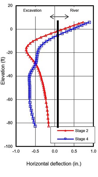
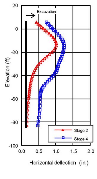
For each stage of construction, nodal displacements, strains, and stresses from the previous stage were set as the initial state values and then updated based on analysis of the current stage. Removal of materials and dewatering was simulated by excavation elements with internal bracings activated for each stage. Selected profiles of sheet pile bending moment and deflections are shown in the three plots. The FEM analysis resulted in the elimination of a costly tieback along the landside, the removal of two rows of internal bracing tiers, and the reduction of the sheet pile embedment length from 120 ft to 90 ft.
Our Comprehensive Project Workflow: Step-by-Step Guide
Initial Consultation and Client Needs Assessment
Our team responds promptly to your inquiries, ensuring timely communication and immediate attention to your project needs. We work closely with clients to understand all project requirements, ensuring that we capture every detail and objective from the start.
Development of Work Plan
Our expert project managers extend innovative problem-solving to project planning, resulting in technically-sound, cost-effective work plans to better serve our clients.
Project Proposal and Agreement
We provide a detailed project proposal outlining the scope of work, fee schedule, and agreement terms. The project begins once the proposal is approved.
Execution and Quality Assurance
Our highly skilled team of principals, project managers, engineers, and field staff execute the project with precision, maintaining open communication to ensure alignment with client expectations. Each project undergoes a rigorous quality check by our team of licensed professional engineers, ensuring all deliverables meet our high standards of excellence.
Project Delivery and Invoicing
Upon completion, we deliver the final project and issue an invoice for the completed work, ensuring full transparency and satisfaction.


